Showing posts with label 5 axis cnc router for sale uk. Show all posts

Wednesday, July 18, 2018

Edge Banding Machine from Roctech to Create Cabinet CNC Production Line

Roctech Machinery Co. Ltd has been commited to the R&D, production and sales of Cabinet CNC Router and Cabinet CNC Production Line for years. We can provide high quality, multifunctional CNC Routers for customers home and abroad. After several years of rapid development, we have diversified products that can provide optimal CNC solutions for our customers.

Now we can offer our customers with diversified products like 5 axis machining center, 4 and 3 axis machining center, woodworking and aluminum processing centers, general 3 axis ATC and manual tool changing engraving machines, EPS processing center and CNC plasma and laser cutting machines. Our CNC router machines have the following advantages: good structural rigidity,high efficiency, high cutting speed, high accuracy with low kerf loss and high quality trimming. And they are also environment-friendly with low noise, less power consumption, high stability,easy maintenance and low maintenance costs. All our products have independent intellectual property right. We have got 10 patent certificates and passed the CE and ISO9001 certificates and UL and PDL product certifications.

Edge banding machine RC-E05 Cabinet production line

1. Function of Wood Edge Banding Machine Gluing→end trimming→ rouh trimming→fine trimming→scraping→buffing


NO.DescriptionParameter
1Technical parameterRC1325FS
2The thickness of edge handing tape0.4-3mm
3The width of edge handing tape12-60mm
4Panel length≥120mm
5Panel width≥80mm
6The feding speed1200-2000mm/min
7Feeding motor1.5KW
8End trimming motor0.37KW
9Rough trimming motor0.7KW
10Fine trimming motor0.7KW
11Polishing motor0.25KW
12Glue box heater2KW
13Air presses to side2KW
14Total power9.4KW
15Weight1700KG
16Size of appearance4600*900*1600mm


For the best Cabinet CNC Router and Cabinet CNC Production Line with the best price, go straight to Roctech Machinery Co. Ltd.

Tuesday, July 3, 2018

Roctech Cabinet CNC Router RC1325S-ATC is Ideal for Wood Cutting

Roctech Cabinet CNC Router RC1325S-ATC is Ideal for Wood Cutting

Roctech Machinery Co. Ltd has been commited to the R&D, production and sales of Cabinet CNC Router and Cabinet CNC Production Line for years. We can provide high quality, multifunctional CNC Routers for customers home and abroad. After several years of rapid development, we have diversified products that can provide optimal CNC solutions for our customers.


1. Syntec Controller, Yaskawa Servo Motor and Driver, Italian HSD Air cooling ATC spindle. 2. CarouselTool Magazine, saving more processing time than traditional ones. According to different work, we can provide the carousel tools.

                 1. Syntec Controller, Yaskawa Servo Motor and Driver, Italian HSD Air cooling ATC spindle.
                     2. CarouselTool Magazine, saving more processing time than traditional ones. According to
                         different work, we can provide the carousel tool magaine with 8,12 or 16 tool holder forks.
                     3. With automatically pushing function, it can connect the auto loading and unloading platform, 
                         for reducing labor cost and saving time.
                    4. Intelligent processing cross-border protection function can prevent the excessive processing
                         caused by mechanical collision.
                    5. Furniture: wooden doors, cabinets, mold industry and advetising.
NO.DescriptionParameter
1Technical parameterRC1325S-ATC
2X,Y,Z Traveling1300*2500*150mm
3TableDouble Layer Vacuum Table
4FrameWelded Structure
5X,Y,Z Drive SystemX,Y Helical rack and pinion, Z Ball screw
6Max Rapid55000mm/min
7Max Working Speed20000mm/min
8Spindle Power9.0KW
9Spindle Speed0-24000RPM
10Driving SystemYaskawa Servo Motors
11Working VoltageAC380V, 50/60Hz, 3Hp
12Command LanguageG Code
13Operating SystemSyntec Control
14SoftwareUG,POWERMILL,ARTCAM,TYPE3
15Gross Weight3450KG
16OptionsVacuum pump


For the best Cabinet CNC Router and Cabinet CNC Production Line with the best price, go directly to Roctech Machinery Co. Ltd.

Tuesday, July 25, 2017

Will CNC Routers End Wood Craftsmanship?

According to Roctech, for hundreds of years, fine woodwork was associated with doing the job by hand. Intricate picture frames, exquisite furniture details, and ornamental wall medallions required hours of painstaking labor. But how intricate woodwork was performed started to change in the 1970s, when modern Computer Numerical Controlled (CNC) routers became widely available.


In the roughly 40 years since their inception, computer-controlled routers have largely taken detailed woodwork out of the hands of craftsmen and placed it on the automated production line. The reason why is obvious: Not only is the quality of the work often as good as what hands can create, but it can be produced in a matter of minutes.
At first glance, it may seem as if purchasing used CNC routers encourages the death of wood craftsmanship, but that isn’t the case. Just because using a quality used CNC router machine makes the production of intricate woodwork faster and more affordable doesn’t mean it compromises the artistry of the one who creates it.

Craftsmanship in Perspective

Big woodworking startups that plan to mass produce simple designs are known for purchasing used CNC routers, but so are craftsmen of unique woodwork who wish to increase production capacity without compromising work quality. Using a computer-controlled router doesn’t downgrade the work; it merely helps the craftsman produce more of it, and earn more money.
Consider the case of G. Watson Designs in Durham, North Carolina, which offers turnkey designs and fabrication services to distinguished clients. In terms of artistry, much of the company’s millwork is comparable to the hand carved work one would find in a fine, baroque residence. However, a machine produces much of the work – a Laguna 5’ X ’10 CNC router, to be exact.

G. Watson Designs has observed in computer-controlled equipment what other woodworking companies have seen: the price of the hardware has consistently dropped, while the quality of its work has continually improved. Investing in a quality used CNC router machine can be more than a good move financially. It can also ensure that great designs are flawlessly executed.

Sunday, July 23, 2017

Testing a low cost CNC Router

Furniture maker, Curtis Erpelding testing and tuning the Maslow CNCROUTER
The Maslow CNC ROUTER is a CNC ROUTER kit that costs just $350. For that price, you should expect a few compromises. For one thing, you have to put it together. Of course you’ll get the key mechanical, electrical and electronic parts, however, you will need to provide plywood and a couple of 2” x 4”s to complete it. The good news, after using one for a while, I can confirm that it really does work but there is one more ingredient you need: “Geekiness.”


After reviewing the beta kit, I think it’s important for potential buyers to approach it with realistic expectations. First, the Maslow is not a plug-and-play CNC ROUTER —not that any current CNC ROUTER is, but the Maslow throws in some extra challenges along the way. It’s a very basic kit mechanically but there are also a few software issues to overcome. What this means is that if you decide to build a Maslow you need to be prepared to step in and solve a few problems as they come up.
Because of my schedule, I was unable to build the kit, so fellow furniture maker Curtis Erpelding got my beta unit up and running. 
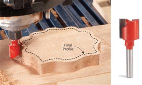
We’ve found that within reasonable limits, the Maslow CNC ROUTER does indeed do what it promises. It takes G-code generated from digital drawings and cuts parts out of plywood or other sheet materials.

Getting the Maslow CNC ROUTER running

Besides building the base — a straightforward construction task for the average woodworker, getting the machine tested and ready presents several challenges. Remember, the Maslow is not “plug and play”. A key task is you need to install the software and test and tune the Maslow. You need to download the current software, install the firmware onto the Maslow’s Arduino-based controller and set up your PC to run the machine. Then you go through several steps to calibrate the machine.
Along the way, you should be prepared to debug problems as they come up. And, being a new device and lightly documented, you should expect a few. This is why I say that potential buyers need to have some geeky skills. If you thrive on these kinds of modern challenges, you’ll be better equipped to solve these kinds of problems than a woodworker who’s experience might be limited to only dealing with mechanical issues.
Thanks to the support from Maslow and its helpful online community, you won’t be alone in dealing with most issues as they come up. Though many of the members of the forum seem to have little CNC ROUTER or woodworking experience, they do appear to have a lot of software experience and they are ready to help if needed.
Maslow Ground Control Software works on PCs, Macs, Linux Machines, some tablets and inexpensive Raspberry Pi computers. The software is simple and easy to use.

Ground Control Software

The Maslow CNC ROUTER controller software is called Ground Control. Keeping with the goal of Maslow to make the CNC ROUTER as accessible and inexpensive as possible, it runs on Windows, Windows Tablets, Macs or even Linux-based Raspberry Pi computers. From a user perspective, Ground Control is simple to use and straight forward. You load the G-code file that you want to run, set a few parameters and away you go.
In its current form, the software is not quite done but getting closer to completion. As I write this, each week a new version of Ground Control is released that solves problems that have been discovered by the many Maslow beta testers. For example, Curtis and I ran into some issues with how the Maslow was rendering and machining circles and curves. It was cutting short arcs instead of the smooth curves that we were expecting. Maslow’s team and the community got on it and fixed the problem. Another issue was the controller was having difficulties reading other flavors of G-code files when I provided RhinoCAM generated G-code files for a test. That quickly got fixed, too. So, you get the idea. If problems come up, between the Maslow crew and the community, you won’t be alone.

Using the Maslow CNC ROUTER

Once you have set up the Maslow, run a few tests and are all ready to go, what’s it like to run the Maslow? The first word that comes to mind — particularly if you have any experience with other CNC ROUTERs is: slow. You can expect a feed rate of 20-35 inches per minute. Dragging a router, held down with bricks, using tiny motors, chains and gears come with some limitations. People have pushed it beyond 35 IPM, but besides obvious mechanical limitations, a key issue is the Arduino’s processor ability to keep up with higher speeds. It can only go so fast.
On top of the slow speed, only shallow cuts should be taken. No, you won’t just plow through a 3/4” piece of plywood in one pass. Think three or four passes. Between the tiny motors and dependence on gravity, there simply isn’t enough torque in the equation to do otherwise. Pushing too hard just adds more resistance. The cost of going too fast or cutting too deep is less accuracy. So, go with the flow and take shallow cuts – about 1/8 to 1/4 deep.
With shallow cuts, the Maslow is fairly accurate. The best approach is to keep your cuts as close to the center of the large Maslow base as possible. In early tests, it was producing samples that were less than 1/32” off square on smaller cuts. With further tuning of the controller software, it seems likely the team will get close to the 1/64” or .4mm design goal. Particularly challenging are long, straight lines. Trying to run lines as long as six or seven feet sometimes produces a bow up to 1/16”. But, being measurable, consistent and repeatable, results could be further improved with more tuning of the controller software on future releases.
A special thank you goes to Curtis Erpelding for all his work building and testing the beta Maslow CNC ROUTER. His base is a top notch design. Simple, flat, rigid and cheap. If you’re building a Maslow, study it!
In the final installment of the Maslow series, I’ll have some suggestions for those considering building a Maslow CNCROUTER.


Monday, July 17, 2017

Step to Step for CNC Router Duplication

CNC Router duplication has been around a long time. Early machines used stiluses to follow the shape of a pattern or master, while on the other end of the machines, routers did the carving. In a similar but computerized fashion, CNC routers are also capable of duplicating existing carvings and furniture parts. A digital “touch” probe is first used in the CNC to sense the surface of the object, while the probe’s accompanying software creates a digital image of the part.


The digital image is then converted to a 3D model and used to program CNC routing paths for a replica. To test the capabilities of this technique, I hand carved a traditional scallop shell measuring about 4
x 4 to use as my original. My test revealed that a CNC digital probe is quite capable of accurately recording the shape of an object, with one exception; due to its ballshaped tip, the probe rounds off the inside corners of fi ne details such as the veins on this shell. A little bit of hand carving easily adds the missing details. The three carvings in the photo below are duplicates of my original (photo above). Watch the digital probe in action at AmericanWooodworker.com/CNC.


Step 1

Set the scanning parameters. The
software control panel is used to set the
size of the scanning area, the precision or
resolution of the scanning action, and the
speed of the scan. The Scan Limits of X and Y
represent the width and length of the scan
area, while the Z Scan Limit represents the
range the probe travels vertically. The Step
Sizes are the X and Y distances the probe
moves between measurements. The Scan
Velocity controls the speed of the probe as
it moves across the part’s surface. The Part
Coordinates show the location of the probe
during operation. I used the Shark CNC Pro
Plus to scan the shell for this article, but
most CNCs, including the CarveWright and
Shopbot, are capable of probe scanning.


Step 2

Scan the part. I set parameters for this shell
carving as shown in Step 1. The X and Y
scanning limits are penciled on the backer
board. The Z limit was set at 1” to provide
sufficient vertical travel for the carving’s 5/8”
thickness. The step sizes of .005” for this shell
equals 800 passes across the shell for a total
of 680,000 steps, or measurement points, and
took about 12 hours. ( I ran this overnight). The
Shark CNC probe has a .075” dia. wear-resistant
industrial ruby tip, so certain details such as the
fine veins on this shell were not fully captured;
but the remainder of the surface was captured
with surprising accuracy. A larger step setting
can be used on objects with less detail, such
as a chair seat. Doubling the step size reduces
scanning time by a factor of four.


Step 3

Adjust the digital image. The
scanning creates an .stl file, which is a
common file type used in 3D modeling.
The scanned area surrounding the shell is
not needed and is removed at this time.


Step 4

Create the 3D model. The .stl file is
converted to a 3D model with CNC
design software such as Aspire by
Vectric. I also used Aspire to increase
the thickness of the shell’s base to 1/4”.


Step 5

Smooth the surface. If needed, the
design software can also be used to
smooth the surface of the model. My
scan was fine enough so I only needed
to remove a couple scratches.


Step 6

Remove the background.
I removed the background to get
the waste material out of the way
in order to make it easier to add the
final hand carved details in Step 10. I
programmed the toolpath for the 3/4”
straight bit at a .1” depth-of-cut per
pass and a stepover (pass width) of .2”.
The tool path was also programmed
to leave the shell profile .125” oversize.
Removing the background for the
three shells took about 30 minutes. The
board started out .875 (7/8” ) thick and
the routed background is .25” thick.
The shell will have a final thickness
of .75”.


Step 7

Rout the final profile and tabs.
The final profile is made using a
1/4” straight bit that cuts all the way
through the material. Tabs are left to
hold the shell in place. These tabs can
also seen in bottom photo on page 15.
A piece of plywood underneath
protects the metal machine bed from
damage. I programmed the toolpath
for the 1/4” straight bit for .125” depth
passes. The profile and tab routing of
the three shells took about 8 minutes.


Step 8

Rough rout the shape.
To accomplish the rough routing I
used a 1/4” ballnose bit programmed
to a .1” depth of cut and .1” step over
(pass width). This roughing phase
removes the majority of the material.
The amount of material left by the
rough pass is adjustable, with .02” being
common for a carving such as this shell.
Leaving this small amount allows the
final pass to be completed in one pass,
saving time and wear on the finishing
bit. The rough routing of the three
shells took about 60 minutes.


Step 9

Rout the final pass.
The final carving is done with a
specialty .0625” (1/16”) ballnose bit
(available at BeckwithDecor.com). I
programmed this bit to make .01” wide
(1/100”) passes. The tiny tip of this bit
is capable of recreating a considerable
amount of detail, and leaves a surface
that only requires a light sanding with
220 grit sand paper to make it ready for
finishing. The final routing of the three
shells took about 70 minutes.


Step 10

Detail by hand as needed.
Complete the carving with some touchup
hand carving of the veins and finish
sanding. There are CNC operations
where the goal is to create a part that
requires no additional hand work—this
application is not one of them. A CNC
is a tool capable of many things, but a
realistic expectation of what it can do
is also important. In the case of these
shells, I accepted the fact that I would
need to do some hand detailing to
achieve the results I wanted, similar to
scraping or sanding a board after
jointing and planning.


Step 11

Make the boxes. After making the
shells, the box shape is simple to
program using the profile of the shell
as a pattern. It took about 150 minutes
to rout the 3 boxes on the CNC using a
1/4” up-spiral bit. They were cut out of
1-1/2” material.


Project Time Card

CNC the lids: 55 minutes each
CNC the boxes: 50 minutes each
Set up and material prep: 15 minutes each
Detailing and sanding: 45 minutes each
Staining and finishing: 20 minutes each
Total time: 3 hours 30 minutes each
I spent 5 hours 15 minutes (total for all three)
doing something else while
the CNC Router ran.


Thursday, December 29, 2016

5-Axis CNC Routers

multi-axis capability is affordable.

The Roc-tech 5-Axis CNC Router is ready for production cutting, drilling, trimming, as well as prototype-and fixture-machining in a large work envelope, accessible from all angles.
5-Axis CNC Router is built on rigid modules with extended height that allows good 5-axis reach. The X axis is a moving table based on the innovative system. The Y axis makes use of the precision extruded beam.

The tool is perfect for 5-axis machining of soft materials such as urethane foams, as well as trimming, drilling, and slotting operations in a variety of materials such as vacuum formed ABS. It is capable of light machining in soft woods, but does not have sufficient rigidity for machining of hard-wood or aluminum.All 5 axes are powered by advanced technology,closed-loop, alpha Step motors providing production speed and precision. The tool includes a 2.2hp HSD spindle fit to the 5-axis head. The 5-axis head, or wrist, utilizes 2 motors. These are “hollow rotary actuators” providing a wide rigid base and stable motion for the two additional axes of rotation.