Wednesday, April 26, 2017
Roctech CNC Router, fully auto nesting, loading and unloading
http://www.roc-tech.com/product/product52.html
Use a CNC Router for boring, milling, drilling and routing
http://www.roc-tech.com/product/product35.html
Final Exercise for CNC Router Learning
The
vinyl cutter is a versatile piece of equipment. It can be used for a range of
work including cutting out packaging nets / developments. It will cut or
perforate card making it easy to fold packages accurately. Craft Robo and Stika
Machines are examples of vinyl cutters.
Complete
the exercise below.


Try Small Scale Production, Manufacturing Nets / Developments in Industry
In actual
industry, packages are manufactured by industrial machines. They are first
designed on a computer system using COMPUTER AIDED DESIGN software (CAD). A net
/ development can be drawn more accurately by CAD software and also checked,
with faults can be corrected before any material is cut, Small companies use
software such as Techsoft 2D design, Coral Draw or other specialist software.
The
software is used to control the cutting equipment.
A company
called ‘Roland’ manufacture a range of machines that are computer controlled.
They are capable of cutting out accurate nets and even scoring the fold lines,
making it easy to fold the net together. A simplified version of one of these
machines is seen below.
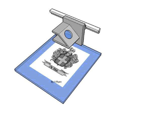
Roland produce a series of machines called STIKA machines. These
are basically used for cutting out adhesive backed lettering for signs and
logos (Material called 'sticky backed vinyl'). However, larger versions can be
used to cut out nets / developments from a range of card. The small hardened
steel cutter is held firmly in a tool holder. The tool holder moves up and down
a slide, following the design. The paper/adhesive laminate is fed into the
machine automatically. As the tool holder moves the cutting tool is pressed
into the material, cutting the desired shape.
These machines are suitable for cutting small numbers of developments/ nets.
These machines are suitable for cutting small numbers of developments/ nets.
4. The computer (including software), vinyl cutter and
manufactured package, can be viewed as a Systems Diagram, see below. Systems
diagrams are divided into three aspects/stages - INPUT - PROCESS - OUTPUT. The
systems diagram below, describes what happens at each stage, from the design to
manufacture of a simple package.
QUESTIONS:
1. Use Computer Aided Design (CAD) to design a small packaging net / development to hold a piece of jewellery.
2. Print out the net and cut out the shape using scissors or craft knife. OR use a computer control cutter such as a STIKA Machine.
3. Add suitable colour, shade, printing styles etc......
wood CNC router
CNC router machine
CNC Router 4 axis
CNC Router 3 axis
cnc router
5 axis CNC Router
Graphics Examination Questions about CNC Router Learning
This question is related to Computer Aidedmanufacture (CAM)
|
In a typical school graphics
room the machine seen below can manufacture ‘‘sticky’ symbols and text for
labelling packaging and displays.
|
|
|
|
|
|
What is the correct name for
the device: _________________________________________
|
|
|
|
|
|
Name the material that it
normally cuts: _________________________________________
|
|
|
|
|
|
When in use the cutter moves
along two axis. The ‘X’ axis is already labelled. Label the ‘Y’ axis on the
drawing.
|
|

|
When manufacturing a product
many times, computer aided manufacture (CAM)
can be an advantage. List three advantages of using CAM.
|
|
|
|
|
|
|
|
ADVANTAGE 1:
|
||
|
|
||
|
|
|
|
|
ADVANTAGE 2:
|
||
|
|
||
|
|
||
|
ADVANTAGE 3:
|
||
|
|
||
|
|
||
|
When designing a product
many times computer aided design (CAD) can
be an advantage. List three advantages of using CAD.
|
||
|
|
|
|
|
ADVANTAGE 1:
|
||
|
|
||
|
|
||
|
ADVANTAGE 2:
|
||
|
|
||
|
|
||
|
ADVANTAGE 3:
|
||
|
|
||
|
|
||
Tuesday, April 25, 2017
Try Small Scale Production, Manufacturing Nets / Developments in Industry
In actual
industry, packages are manufactured by industrial machines. They are first
designed on a computer system using COMPUTER AIDED DESIGN software (CAD). A net
/ development can be drawn more accurately by CAD software and also checked,
with faults can be corrected before any material is cut, Small companies use
software such as Techsoft 2D design, Coral Draw or other specialist software.

The
software is used to control the cutting equipment.
A company
called ‘Roland’ manufacture a range of machines that are computer controlled.
They are capable of cutting out accurate nets and even scoring the fold lines,
making it easy to fold the net together. A simplified version of one of these
machines is seen below.

Roland produce a series of machines called STIKA machines. These
are basically used for cutting out adhesive backed lettering for signs and
logos (Material called 'sticky backed vinyl'). However, larger versions can be
used to cut out nets / developments from a range of card. The small hardened
steel cutter is held firmly in a tool holder. The tool holder moves up and down
a slide, following the design. The paper/adhesive laminate is fed into the
machine automatically. As the tool holder moves the cutting tool is pressed
into the material, cutting the desired shape.
These machines are suitable for cutting small numbers of developments/ nets.
These machines are suitable for cutting small numbers of developments/ nets.

4. The computer (including software), vinyl cutter and
manufactured package, can be viewed as a Systems Diagram, see below. Systems
diagrams are divided into three aspects/stages - INPUT - PROCESS - OUTPUT. The
systems diagram below, describes what happens at each stage, from the design to
manufacture of a simple package.
QUESTIONS:
1. Use Computer Aided Design (CAD) to design a small packaging net / development to hold a piece of jewellery.
2. Print out the net and cut out the shape using scissors or craft knife. OR use a computer control cutter such as a STIKA Machine.
3. Add suitable colour, shade, printing styles etc......
1. Use Computer Aided Design (CAD) to design a small packaging net / development to hold a piece of jewellery.
2. Print out the net and cut out the shape using scissors or craft knife. OR use a computer control cutter such as a STIKA Machine.
3. Add suitable colour, shade, printing styles etc......
From Theoretical Design to Practical Manufacture on Laser Cutting / Etching Machines
A laser cutters / etching machine will cut, etch
and shape a range of materials with great precision. The process is started
with the designer using a vector or bitmap drawing package such as Corel Draw
or Corel Paint. A design is produced and saved in the normal way.

When the drawing is ready to be etched or cut and
shaped on a laser machine, the file menu is selected and from this the print
menu and sent to the laser cutter in the same way as sent to a printer.

The computer is normally connected to the laser
cutter via a USB connector. The file is transferred from the computer to the
laser cutter. The laser cutter converts the design into coordinates and it is
these that are used to move the laser lens system to the correct positions when
cutting takes place.

Monday, April 24, 2017
Introduction to Laser Cutting / Etching Machine -Part 2
Although seemingly high end, classy
and high grade, laser cutting / etching machines are quite simple in the
way they work. The lens system that controls the position of the laser is
itself moved by a motorised slide control system. This allows movement in any
direction. The control system moves according to the programme being used by
the machine. The diagram shows the LID open - however, the laser will not
operate unless the lid is closed. This is a safety feature.

The work/material being engraved or cut by the
laser is held firmly in position on a vacuum bed. The work/material is normally
positioned in the top left corner as shown on the diagram below. The machine
operates with three axis, X, Y and Z. The top left corner is regarded as
coordinates (0,0,0), this is sometimes called zero point or the start point.

The diagram below shows a coat of arms being etched on a sheet of transparent glass. The lens unit focuses the laser in exactly the right position as it cuts / etches.


A close up of a typical lens system can be seen
below. The lens system slides up and down the motorised slide control system.

The laser is deflected from it source within the
machine through a series of precision lenses/mirrors and focussed accurately on
the area to be cut/etched. The laser removes small dots of material, up to 1200
dots per inch. This means that it is able to cut extremely accurate shapes and
produce astonishingly detailed etchings. The laser cutter is similar to an ink
jet printer. The printer sprays ink onto the paper in a series of dots that
make up a picture or text. The laser cutter removes material in a series of
dots producing pictures / etchings and shapes cut away from the surface of the
material.

|
The microprocessor
controlled height guide ensures that the laser cuts to the correct depth.
|
|
|
|
|
|
If a circular or curved
product such as a glass container is to be etched then a motorised roller
system is used. The rollers are controlled by the microprocessor, rotating
the glass at exactly the right speed and direction. This allows etching to be
produced accurately on the surface. The height guide ensures that the laser
is set to the correctly at all times. This system allows uneven surfaces to
be etched as well as surfaces that are uniform.
|
|
Introduction to Laser Cutting / Etching Machine -Part 1
Although the first industrial machine was
introduced in 1988 by a USA based company called EPILOG, laser cutting and
etching machines are relatively new in schools and colleges. Laser cutters/etching machines are capable of very accurate work as a laser is used
to etch or cut material precisely. They can be used in the cutting/ shaping of
precise parts for prototype architectural models and etching a range of
materials such as glass, marble, woods, plastic and even stainless steel.

A framed engraving of a family coat of arms is
shown below. Inside the wood frame is a small sheet of glass and the coat of
arms has been engraved/etched into the top surface using a EPILOG laser cutter
/ engraver. Before the introduction of laser cutters this process would have
taken a considerable amount of time and the coat of arms would have been
engraved by a skilled craftsperson, using a range of sophisticated glass
engraving tools.

The laser cutter / engraver uses a laser ‘beam’ to etch the shapes to precisely the correct depth. The laser machine takes a fraction of the time to manufacture a piece of work of this type compared to traditional methods.


The laser cutter / engraver uses a laser ‘beam’ to etch the shapes to precisely the correct depth. The laser machine takes a fraction of the time to manufacture a piece of work of this type compared to traditional methods.

LASER CUTTING STEEL PLATE

More
examples of objects engraved / cut using a laser cutter/etching machine are
shown below.

A typical Laser Cutter / Etching Machine is shown
below. The example shown is no larger than a typical photocopier. A vacuum bed
holds the work to cut/ engraved securely and the lens system directs the laser
as it cuts / etches the material.
The way to Export STL Files From CAD Software
When manufacturing a product / a model using a 3D printer, the first
stage is to design and draw it in CAD software.

Once completed, the design will be exported as an STL file ( or OBJ / DAE
/ AMF formats), which is likely to be compatible with the software provided by
the 3D manufacturer. Some 3D manufacturers use open source software such
as ‘CURA’.

Open up the manufacturers recommended software and import the STL file.
The design can then manipulated, such as rotated and scaled. It is then
ready for saving as a model.
The model (file) can then be copied to an SD card, which in turn is
inserted into the 3D printer SD-card slot, ready for use.
Introduction of Using 3D Printers for Filament Spool
3D printing is already a process, whereby 3D CAD designs are
manufactured on machines capable of producing a solid form / model.

3D printing has already been as important as an industrial process, especially in the production of some tools, textiles, toys, jewellery and a range of components. The technology also has been used in the medical world, in the manufacture of custom made prosthetic limbs and hearing aids. It even has a practical application in the world of dentistry. Research has been taking place for several years on ‘bioprinters’. These are complex 3D printers, capable of printing bio-structures, used in surgery.

The cost of 3D printing machines is falling and it is now possible for
most hobbyists and educational establishments interested in this area, to
purchase cheap and reliable machines. An example of a typical 3D printer is
seen below.

3D printers construct a ‘model’ by building up layer upon layer of PLA,
Nylon or ABS, fed from spool, usually at the back of the printer. Each layer is
a fraction of a millimetre and building even a small model can take some time.
The PLA / ABS is purchased in the form of filaments on open spools (see
opposite). Filaments tend to be 2.85mm diameter (known as 3mm filament), rolled
on to a spool. The spool fits on a roller, normally on the back of the 3D
printer.

The ABS /PLA is heated as it is drawn through the print head, which moves
side to side. As the print head moves, it lays down a layer. This is slowly
built up, producing the final 3D object. Different resolutions can be selected,
depending on the quality of model required (e.g. 20 micron (Ultra high), 60
micron (High), 100 micron (Medium), 200 micron (Low))

Sunday, April 9, 2017
List of More Advantages OF A 3D Modelling and Questions
Advantages:
1. Complete 3D models can be manufactured,
including those models with hollow parts which could not possibly be made by
hand in one piece, even by the most sophisticated engineers or craftsperson.
Parts such as bearings, engineering parts and complex working models can also
be manufactured.
2. A variety of resins and waxes can be applied to the completed model. These increase the strength of the model, its temperature resistance and also allows paint and finishes to be applied realistically.
3. A two part urethane can be added to the model to give it the properties of rubber.
4. Models can be electroplated so as to give the look, feel and gloss of a range of metals.
5. Prototyping machines such as the ZPrinter 310 can even be utilized to produce highly accurate patterns for casting.
6. Manufactured model parts can be combined with real parts to produce a fully functioning product that can then be tested and evaluated

QUESTIONS:
1. What are the advantages of making an accurate model of a prototype using a 3D printer?
2. Draw a simplified sequence drawing of the stages involved in making a prototype using a machine such as the Z310 3D printer (from Z-Corporation). Add notes to help explain each stage.
3. What is the meaning of the term C.A.D. ?
4. How does making a 3D model of a product help a design team develop the product?
5. Research 3D modelling machines using the internet. Collect information such as the cost of machines, where they are made and what they are capable of producing. Include pictures/photographs.
6. Do you think that sometimes there is no need to use an expensive piece of equipment such as a 3D printer to make a model? Explain your answer.
cnc routers for woodworking
cnc router for sale
cnc router 2040
cnc router kit
homemade cnc router
cnc wood carving machine price
cnc wood carving machine reviews
cnc router machine price in india
cnc drilling machine price
cnc drilling machine wiki
cnc drilling machine manufacturers
cnc drilling machine for sale
4 axis cnc router price
4 axis cnc wood router
4 axis cnc router projects
4 axis cnc machine for sale
4 axis cnc mill
4 axis cnc router for sale
4 axis cnc router kit
How to Manufacture a Model Using the 3D Printer
The model which is to be manufactured is to build up one layer at
a time. A layer of powder will be automatically deposited into the model tray.
The printer head will then apply resin in the shape of the model. The layer
dries solid almost immediately. The model tray then moves down the distance of
a layer and another layer of power will be deposited in position, in the model
tray. The printer head again applies resin in the shape of the model, binding
it to the first layer. This sequence occurs one layer at a time until the model
is fully completed.


cnc router for sale
cnc router 2040
cnc router kit
cnc wood carving machine price
cnc wood carving machine reviews
cnc drilling machine price
cnc drilling machine wiki
cnc drilling machine for sale
cnc drilling machine india
diy cnc wood router
4 axis cnc wood router
4 axis cnc router projects
4 axis cnc machine for sale
4 axis cnc mill
4 axis cnc router for sale
4 axis cnc router kit
diy 4 axis cnc router
cnc router price
cnc router kit
laser metal cutting machine
laser wood cutting machine
Subscribe to:
Posts (Atom)